
Aerodynamics Investigative Project- Effects of Surface Roughness on the Aerodynamics of wing
I was extremely enthusiastic about this project as it was my first experience of understanding the principles of aerodynamics. It was one of those projects that I wanted to experiment and was assigned the same. This a project gave me a beautiful insight to understanding the core importance of aerodynamics in racing car and the aircraft industry. My module, aerodynamic design which was a part of my course, provided me better insights into pursuing this project. This project was carried out in five steps. The steps involved were Design, Manufacturing and Assembly, Wind Tunnel Experiment, Data interpolation, and Report conclusions. In this page, I've explained each of the steps and technical considerations respectively.
Although surface roughness has been known to have significant effects on the aerodynamic performance and many researchers have contributed to the understanding on this topic, further investigation still required due to contradictory experimental results. Hence this project was carried out to contribute to the investigation of the effects of surface on the aerodynamics of wing.
*Skip to the bottom of the page to view the report including computation and design.
Brief Summary
During the project tenure, I:
-
Conducted detailed design work for the wings on Fusion 360 and SolidWorks, ensuring that they met the project's objectives. This involved making critical technical decisions regarding wing selection and considering various factors such as surface roughness to optimize aerodynamic performance.
-
Ensured that the wings were constructed according to precise specifications using 3D printers and laser cutting machines.
-
Assembled the components for structural integrity and readiness for testing.
-
Designed wind tunnel test protocols to examine the effects of different surface resistances, Reynolds numbers, and angles of attack on lift and overall aerodynamic performance.
-
Monitored and calibrated the wind tunnel during the whole process.
-
Collected comprehensive data during experimental testing, forces in the x, y, and z directions via LabView.
-
Performed data interpolation using MATLAB to calculate lift and drag coefficients, enabling detailed aerodynamic analysis.
Project Outcomes:
Through rigorous experimentation and analysis, I derived valuable insights into the relationship between surface roughness and wing aerodynamics. I was able to draw conclusions regarding the impact of surface roughness on lift generation and overall wing performance. Overall, this project contributed to advancing our understanding of wing design optimization and provided valuable insights for future aerodynamic research and development efforts.
Comprehensive Explanation
Fundamentals
A streamlined body passing through a fluid generates a boundary layer due to the friction between the air particles and the body's surface. This boundary layer, essentially a thin layer of fluid, significantly influences drag, heat transfer, and overall aircraft performance.
Consider an ideal scenario where the streamlined body has a perfectly smooth surface, devoid of any surface roughness or external disturbances. In this case, the flow over the body remains laminar, as there are no disruptions to induce turbulence. However, the introduction of disturbances such as surface roughness, dust particles, or ice causes the flow to transition from laminar to turbulent. This transition, known as laminar flow separation followed by turbulent flow, leads to a loss of smoothness in the flow pattern.
In the context of this project, I investigated whether introducing surface roughness delayed the onset of turbulent flow. This exploration aimed to determine if delaying turbulent flow resulted in a larger lift curve, delayed stall, and improved efficiency.
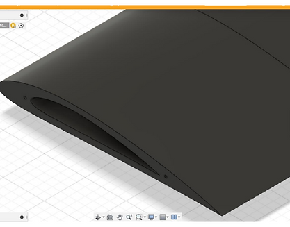
Design
The design of this project this influenced by several factors including wind tunnel size, materials availability, time constraints, budget and deliverability, etc.
-
Wing- NACA 4412, cambered air foil, rectangular shape
-
Material- PLA for wing and Acrylic for endplates
-
Endplates- Elliptical
This particular NACA code was used as it stands as a best performer under this civilian aviation standards. It is also to be noted that a cambered air foil generates lift due to its curvature of streamline body. The materials were often out of ready availability and budget. Endplates were necessary to reduce the wing tip vortex due to the escape of gaseous fluid from increase pressure on low surface of the wing to decrease pressure on the upper surface of the wing.
In order to introduce surface roughness, grid strips were used along the span of the wing and between the front and center of the chord line. The reason being, certain researches suggested that a rough surface in the laminar region, creates a turbulent separation bubble which detaches and reattaches to the surface to continue a short duration of laminar flow and eventually a turbulent flow. This was seen to provide higher lifts.

.png)
Manufacturing and Assembly
-
Wing- 3D printed. It was divided into 5-7 individual sections
-
Endplates- laser cut
Although the manufacturing was fairly simple, there was a major conflict in selection of material between PLA and epoxy resin. Due to constraint of budget PLA was selected but if epoxy resin were selected, the smooth surface texture compared to PLA would have complemented best results.
The parts were assembled using steel rods and hot glue/ super glue with clamping over several days to secure the structure.
Constraints:
-
Using PLA which is known to have high degree of roughness
-
Opting for 3D printing as manufacturing method which meant uneven distribution of weight to a minor level, infill error, snapping, and wrapping
.png)
Wind Tunnel Experiment
For the purpose of this experiment, an open wind tunnel of dimension 1.2m x 1.2m x 3m with closed test section was operated at atmospheric static pressure. It had a mesh layer with honeycomb structure to ensure uniform flow inside the wind tunnel. Angle changing unit was at the bottom of the wind tunnel connected to steam rod in the center. The maximum safe velocity for the project was 16 m/s which was measured using the pitot tube at the beginning of the test section. This was reflected on digital micromanometer.
The load cell held the wing and collected necessary data based on specific tension applied to the wing at varying axes. The data was collected at a frequency of 10,000 Hertz.
Constraints:
-
Load cells sensitivity
-
Wind tunnel mesh arrangement
-
Angle of attack accuracy

Data Processing
Initially the raw data from the LabView software was collected. This meant that at a frequency of 10,000 Hertz, as many recorded data was stored into files. After considerations of average and settling time for each condition (Example: a value for Grit 1 at a certain Reynolds number and specific angle of attack would make 1 condition). There were 90 such conditions and MATLAB saved the day! This was then subjected to angle of attack calculations as the load cell's X and Y direction did not consider the angle of attack effects. This provided the data for lift, drag, left coefficient, and drag coefficient.
Constraints:
-
Manual timekeeping of settling time
-
Fluctuations of RPM
-
Deviation of wind tunnel velocity
There were many other alternatives eliminate systematic errors such as MDOE and OFTA, the details of which I mentioned in the report attached below.
.png)
.png)
.png)
Report & Conclusions
The smoothest wing, which in this case was considered to be the surface of the wing itself, provided better lift. Addition of surface roughness did not improve the lift curve and the drag was increased gradually.
Reynolds number improves the aircraft performance with positive zero lift coefficient curve the higher Reynolds number considered in this experiment provided better lift. The downside was increased drag with steady increase of Reynolds number.
For this wing condition the stall was observed between 12 to 15 degrees of angle of attack.
It must also be noted that all the conditions provided a lift and drag curve but hand pickable conditions showed the most efficient performance.
Constraints:
The smallest wing in this project itself had certain degree of roughness which could have slightly lower lift curves compared to the external researchers
.png)
.png)
.png)
.png)
.png)
.png)
.png)
.png)
.png)
Although this project focused on experimental evidence, simple simulations were done on the model using ANSYS to understand the basics of Simulation involved in aerodynamics. This venture gave rise to further questions such as:
What affects the surface roughness have on different air for shapes?
How can surface roughness be correctly defined?
Would introducing a surface roughness in different locations of a wing increase efficiency or not?
Would increasing roughness purposefully by adding vortex generators or riblets contribute to better performance?
Along with further research questions, I was piqued to explore the simulation analysis involved in aerodynamics. This led me to explore OpenFOAM and ANSYS.
.png)
.png)
.png)
.png)